
Entity Cookbook
Examples of common entity shapes, as YAML files you can download and push
The hydris data model is extremly flexible, covering all domains and maps to many down and upstream standards. The flexibility can be overwhelming, so here's a few very concrete examples of how the system is intended to be used. Note that while these are showing screenshots, the end goal of an integration is never to just show things in the hydris UI. Maximize the use of builtin transformers instead of drawing things directly, so hydris can translate your original intent the way a downstream system understands it.
Every example is a valid input to hydris ec apply, which takes a file of one or more entities and pushes them:
# from a file
hydris ec apply camera.yaml

# straight off this site
curl -sL https://projectqai.github.io/examples/camera.yaml | hydris ec apply -
Static picture
A point on the map
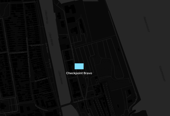
The smallest useful entity. geo gives the position and symbol draws it. routing lets it leave the node. An entity without routing stays local, which is how device and configuration entities avoid your whole network.
hydris ec apply marker.yaml# The smallest useful entity: a point on the map.
#
# geo where it is
# symbol how it is drawn (MIL-STD-2525C)
# routing without this component the entity never leaves the local node
#
# push it with: hydris ec apply marker.yaml
id: example.site.cp1
label: Checkpoint Bravo
geo:
latitude: 54.1782
longitude: 12.0895
altitude: 12
symbol:
milStd2525C: SFGPU-----
routing:
channels:
- {}Zones and volumes
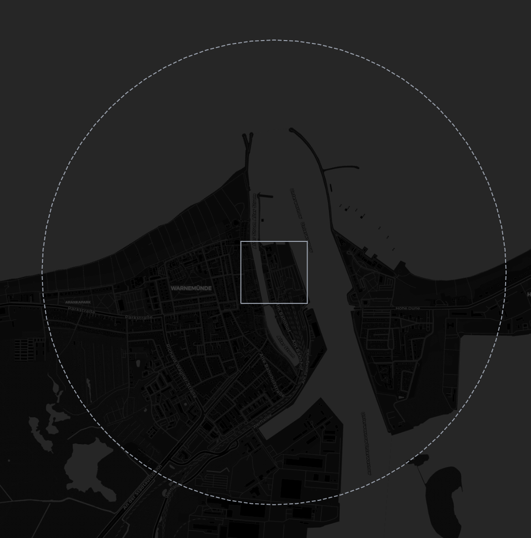
An outline is a shape entity. It holds no geo of its own, because the geometry holds the coordinates. Add an extrusion, and the flat outline becomes a volume. Use this for a no-fly cylinder or a building.
hydris ec apply zones.yaml---
# A fenced perimeter as a closed polygon.
# All rings must be closed: the last point repeats the first.
id: example.zone.perimeter
label: Site Perimeter
shape:
geometry:
planar:
polygon:
outer:
points:
- { longitude: 12.0862, latitude: 54.1770 }
- { longitude: 12.0928, latitude: 54.1770 }
- { longitude: 12.0928, latitude: 54.1806 }
- { longitude: 12.0862, latitude: 54.1806 }
- { longitude: 12.0862, latitude: 54.1770 }
---
# A no-fly cylinder: a circle extruded to 120 m.
id: example.zone.nofly
label: No-Fly Cylinder
shape:
geometry:
planar:
circle:
center: { longitude: 12.0895, latitude: 54.1788 }
radius_m: 1500
line_style: LineStyleDashed
extrusion:
height_m: 120
fill:
color: "#ef4444"
opacity: 0.10Map overlays
A tile source or a georeferenced image. The operator can switch each layer on and off.
hydris ec apply map-layer.yaml---
# An XYZ tile source, same template a slippy map uses.
id: example.layer.seachart
label: Sea Chart
map_layer:
z_index: 10
opacity: 0.8
tiles:
url: https://tiles.example.org/seachart/{z}/{x}/{y}.png
---
# A single bitmap, centered on the entity's geo and sized in meters.
# Move the entity and the image moves with it.
id: example.layer.siteplan
label: Site Plan
geo:
latitude: 54.1788
longitude: 12.0895
map_layer:
z_index: 20
opacity: 0.6
image:
url: https://artifacts.example.org/siteplan.png
width_m: 600
height_m: 400
routing:
channels:
- {}Sensors
What makes a sensor an asset
Each sensor below has a device component. A geo and a symbol draw a picture of a thing. A device says that the thing is equipment you own, and that it can be active, degraded or dead:
device:
  class: radar                              # what kind of thing it is
  category: Sea                             # how a UI groups it
  state: DeviceStateActive                  # Pending, Active, Degraded, Failed
  error: sensor buried, calibration overdue # for a human, when the state is not Active
  unique_hardware_id: example.radar.sn-4417 # follows the hardware between ports and nodes
  parent: example.ship.gannet               # its place in the device tree
An entity with both a device.state and a symbol is an asset. That puts it in the readiness panel, and controls whether an operator can task it. Readiness uses three components: geo for position, device.state for the device, and link.status for comms. See Task Assets.
A sensor without a device is only a marker. It can never report that it is broken.
For real hardware, the engine finds the device and writes these entities for you, with the usb, ip, serial, ble etc details filled in. You write one by hand when you are the driver. To make a device configurable, add a ConfigurableComponent with a JSON schema. The user's answer comes back as a ConfigurationComponent on the same entity. See the Plugin Reference.
Detections
A detection is one raw observation from one sensor. It is not a track. It is not fused. Some sensors have built in trackers, but most don't.
A detection usually does not know where it is. A sensor measures an offset from itself, and different sensors measure different amounts. So the detection reports what the sensor measured, and the engine resolves it against the pose of the sensor:
| The sensor measured | What you push | What you get back |
|---|---|---|
| a direction | pose.polar with azimuth and no range | a bearing, no position, and a line of bearing with dotted error lines |
| a direction and a distance | the same, with range | a geo, and a line of bearing that runs to range + 2σ |
| an offset in meters | pose.cartesian with east_m and north_m | a geo and an uncertainty ellipse. A cartesian offset holds no direction |
| a position | geo with a covariance and no pose | the ellipse. An isotropic covariance becomes a circle |
| that something is near | pose.cartesian with a covariance and no offset | the detection on its sensor, inside a circle of uncertainty |
Give the uncertainty once, in the form your sensor produces. Use the azimuth_error_deg fields or the covariance matrix. The engine calculates the other form.
A detection typically has no symbol. Put what the sensor observed in classification.taxonomy, which is a tree that a machine can read. The client that draws the picture then decides how to draw it. A 2525C code is a decision about drawing, and the detector must not make it.
You lose nothing, because the engine calculates a symbol from the taxonomy:
| Taxonomy | Also on the entity | Symbol you get |
|---|---|---|
equipment.sensor.radar | a device component | SFGPESR---. F for friend, because your own equipment carries a device |
equipment.sensor.radar | nothing | SUGPESR---. U for unknown |
person with confidence.pending | nothing | SPGPU-----. P for pending |
| none | — | no symbol, which is correct for a bare radar return |
Cameras
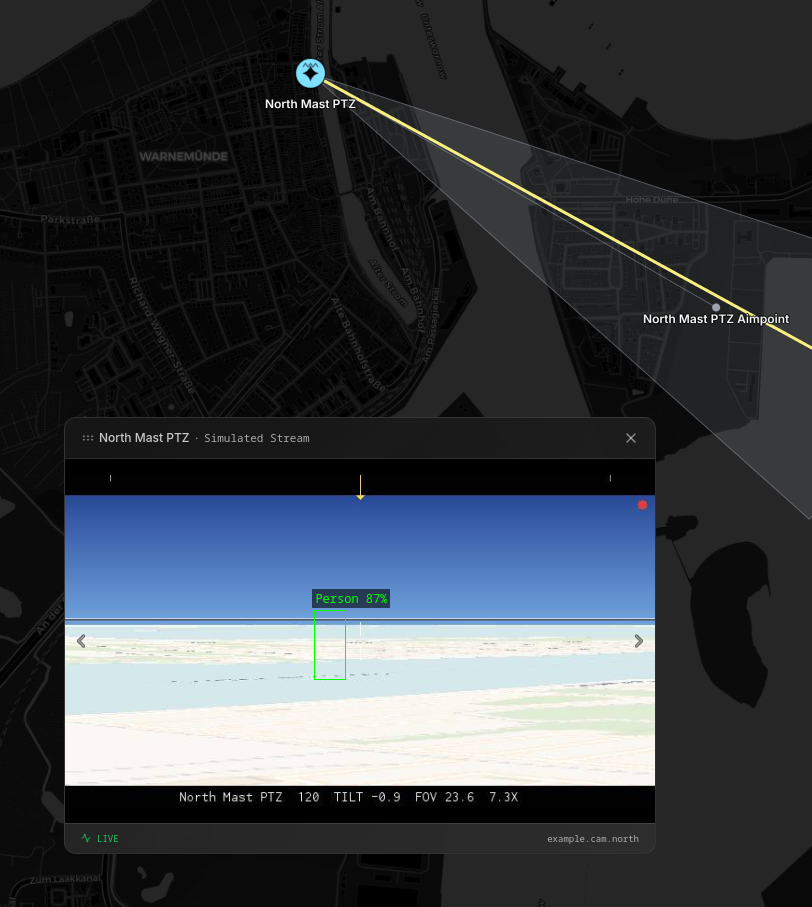
A camera measures a direction, and no distance. The example file holds a mast, the camera, the point it looks at,
The aim point is implemented by the camera driver. A vendor pan/tilt/zoom triple means nothing to other systems, so the aim point is an entity with a position. The driver reports the true direction in pose. A client writes the wanted direction into target_pose. The driver then moves the gimbal until the two agree. To aim a camera and to move a turret become the same operation.
The example also contains a detection as a bounding box. The builtin transformers automatically calculate a LOB from that.
hydris ec apply camera.yaml# A PTZ camera, and everything it produces.
#
# This file builds a working camera on any Hydris node, because it uses the
# simulated camera that ships with the engine. Push it, open the map, and the
# camera renders a live view of the world around it.
#
# Six entities:
# example.mast.north the structure. it holds the only position
# example.cam.north the camera, 16 m up the mast
# example.cam.north~fp the point the camera looks at
# example.det.person1 what the camera saw
# example.artifact.snapshot1 the image that proves it
# example.task.lookat the action an operator can run on the camera
#
# Only the mast has a latitude and a longitude. The children give an offset
# from their parent. The engine walks the tree and calculates the absolute
# position of each child. Move the mast, and all of it moves.
#
# push it with: hydris ec apply camera.yaml
---
# The structure. A mast is not a device. It cannot fail, so it has no device
# component, and it stays a fixture on the map.
id: example.mast.north
label: North Mast
geo:
latitude: 54.1801
longitude: 12.0871
altitude: 6
bounds:
width_m: 1.2
height_m: 18
depth_m: 1.2
classification:
taxonomy:
- confidence:
confidence: 1.0
infrastructure:
tower: {}
symbol:
milStd2525C: SFGPU-----
routing:
channels:
- {}
---
# The camera. 16 m straight up the mast.
#
# This is the whole camera. There is no camera component here, no stream URL,
# no field of view and no symbol, because a driver owns those.
#
# `device.parent` names the driver, and `device.class` says what kind of thing
# to make. `config` holds the settings that the driver asks for. The driver
# then claims the entity and writes the rest: the camera component, the stream
# URL, the focal point, the coverage cone, the symbol and the taxonomy. Read
# it back with `hydris ec get example.cam.north` to see what it added.
#
# `simcam.service` is the simulated camera that ships with the engine, so this
# file works with no hardware. Point `device.parent` at `reolink.service` or
# `axis.service` instead, give it an address, and the same three components
# drive a real camera.
#
# Write only what you know. The driver knows the rest.
id: example.cam.north
label: North Mast PTZ
# east_m, north_m and up_m are meters in the parent's frame
pose:
parent: example.mast.north
cartesian:
east_m: 0
north_m: 0
up_m: 16
device:
parent: simcam.service
class: camera
config:
value:
# widest and narrowest field of view, in degrees. the engine calculates
# the effective field of view between them from the zoom, so the coverage
# cone on the map becomes narrow as the camera zooms in
fov_wide: 60
fov_tele: 8
# how far the camera can see, in meters
range_max: 2000
# a simulator setting: move to a new aim point at once, rather than at the
# speed of a real gimbal
instant_slew: true
# set this to true and the simulated camera produces its own detections
enable_detections: false
# raise this number every time you change the values above. the driver
# echoes it back in `configurable.applied_version` once the change is live
version: 1
---
# Where the camera points.
#
# A vendor pan/tilt/zoom triple means nothing to other systems, so the aim
# point is an entity with a position. The driver creates it, and names it in
# `camera.focal_point`.
#
# The two poses have two different owners:
# `pose` where the gimbal is now. the driver writes it
# `target_pose` where it should be. a client writes it
#
# The driver moves the gimbal until the two agree. So this file writes only a
# target, and the camera turns to it. Push a new `target_pose` and it turns
# again. To aim a camera and to move a turret become the same operation.
#
# The lens is 22 m above the ground, so 0.9 degrees down over 1400 m puts the
# aim point on the ground. `range` is also the zoom: it drives the effective
# field of view between fov_wide and fov_tele.
id: example.cam.north~fp
label: North Mast PTZ Aimpoint
target_pose:
polar:
azimuth: 120
elevation: -0.9
range: 1400
---
# What the camera saw.
#
# A camera measures a direction. It cannot measure a distance, so this entity
# has no position.
#
# It has no angle either. A detector reports the pixel box it found, because
# pixels are what it has. The engine takes the field of view and the frame
# size from the camera, adds the current pan and tilt, and calculates the
# pose. Then it draws a line of bearing with two dotted error lines.
#
# So the bearing follows the camera. Slew the camera with a new `target_pose`,
# push the same box again, and the line of bearing points somewhere else.
#
# A detection has no symbol. `classification.taxonomy` says what it is, and
# the client decides how to draw it.
id: example.det.person1
label: Person
# who made this detection. the engine sets `node`, so do not set it yourself
controller:
id: example.detector.yolo
# detections are urgent. this sends them before routine traffic
priority: PriorityImmediate
detection:
detectorEntityId: example.cam.north
# entity ids that support this detection
evidence:
- example.artifact.snapshot1
# confidence that something is there
confidence: 0.87
# the pixel box in the frame, and the frame it came from.
# the engine needs all six numbers to calculate the angle
image_bbox:
x: 1620
y: 880
width: 210
height: 460
frame_width: 3840
frame_height: 2160
classification:
taxonomy:
- confidence:
confidence: 0.87
person: {}
routing:
channels:
- {}
---
# The image the detector kept.
#
# Files are too large for an entity. Put the file in an artifact entity, and
# refer to its id. Artifacts expire on a lifetime, and the storage backend
# then deletes the file.
id: example.artifact.snapshot1
label: North Mast snapshot
artifact:
content_type: image/jpeg
size_bytes: 184320
sha256: 9f86d081884c7d659a2feaa0c55ad015a3bf4f1b2b0b822cd15d6c15b0f00a08
# where the bytes are. list more than one location if you have copies
location:
- url: https://artifacts.example.org/snapshots/9f86d081.jpg
routing:
channels:
- {}
---
# What an operator can do with the camera.
#
# The driver pushes this entity to advertise the action. A client then calls
# WorldService.RunTask, and the engine creates a TaskExecutionComponent. The
# driver watches for that component and moves the camera.
#
# The task is a different entity from the camera. `assignee` names the camera.
# One camera can offer many tasks.
id: example.task.lookat
label: Look At (North Mast PTZ)
taskable:
label: Look at target
icon: eye
# what the task does, for a human or an LLM to read
effect: turns the north mast camera onto the selected target and holds it there
# a new run replaces the current run
mode: TaskableModeReconcile
assignee:
- entityId: example.cam.north
# the caller must give one entity to look at.
# use `position` for a point, or `waypoints` for a route
target:
entity:
max: 1
# what the task means. a client groups tasks from different vendors by this
taxonomy:
observe:
look_at: {}
# sort order in the menu. high numbers come first
priority: 100
routing:
channels:
- {}Radars
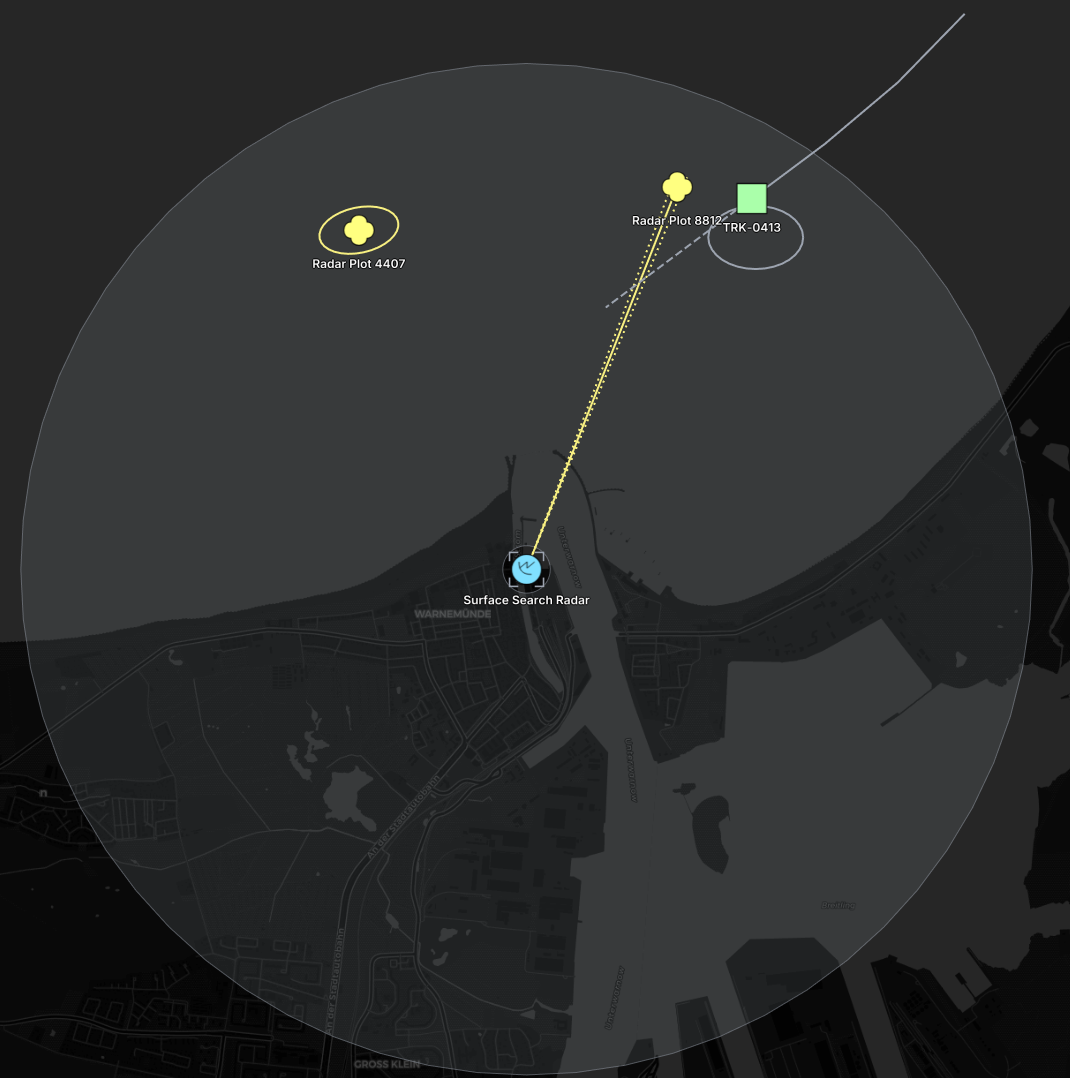
Radars differ in what they give you, and the difference decides what your driver pushes.
A simple radar reports plots: raw returns with a bearing and a range, and no memory from one sweep to the next. Those are detections. Drivers report a plot in three different ways, and the file shows all three.
Many radars associate their own plots and report tracks. Some report both. A radar that reports tracks needs no detections at all: push the track, and name the radar in track.tracker. A consumer cannot tell whether radar firmware or a separate fuser produced a track, and it does not need to.
A track keeps evidence pointers to the plots it used, when it has them, so an operator can ask why the contact exists. Its history and its predicted path are separate shape entities, so a client that needs only the current position does not receive them.
The radar also declares what it can see. A camera gives a fov and a range_max, and the engine builds the cone. No two radars have the same footprint, so sensor.coverage names shape entities instead. It is a list, which lets a radar with a mast in the way declare one shape for each part it can see.
hydris ec apply radar.yaml# A radar, its plots, and the track that fuses them.
#
# Eight entities:
# example.radar.north the radar
# example.radar.north.coverage the area it can see
# example.det.radar.8812 a plot with a bearing and a range
# example.det.radar.8830 a plot as an offset in meters
# example.det.radar.4407 a plot as a position
# example.track.vessel1 the track built from two of the plots
# example.track.vessel1.history where the track has been
# example.track.vessel1.prediction where the track goes next
#
# The three plots show the three ways a driver can report a contact. All three
# use the same detection component. Only the offset changes.
#
# No plot has a symbol. A detection reports what the sensor measured, not how
# to draw it. `classification.taxonomy` says what it is.
#
# push it with: hydris ec apply radar.yaml
---
# The radar.
# The device component makes it an asset with a state. The symbol makes it
# visible. Together they put it in the readiness panel.
id: example.radar.north
label: Surface Search Radar
geo:
latitude: 54.1804
longitude: 12.0884
altitude: 9
device:
class: radar
category: Sea
state: DeviceStateActive
unique_hardware_id: example.radar.sn-4417
link:
status: LinkStatusConnected
avg_latency_ms: 8
# What the radar can see.
#
# A camera declares a `fov` and a `range_max`, and the engine builds the cone.
# A radar has no such fields, because no two radars have the same footprint.
# So the sensor names shape entities that give it.
#
# `coverage` is a list. A radar with a mast in the way, or one that scans a
# sector, names one shape for each part it can see.
sensor:
coverage:
- example.radar.north.coverage
classification:
taxonomy:
- confidence:
confidence: 1.0
equipment:
sensor:
emplaced: {}
radar: {}
symbol:
milStd2525C: SFGPESR---
routing:
channels:
- {}
---
# The coverage.
#
# A ring, not a disc. `inner_radius_m` cuts out the blind zone below the
# minimum range of the radar, so the shape states both limits at once.
#
# The geometry is a `local_shape`, in meters from the radar, so the coverage
# follows the radar. Move the radar, and the ring moves with it. The engine
# converts the ring to WGS84 for clients that want it in world coordinates.
id: example.radar.north.coverage
label: Radar Coverage
local_shape:
relative_to: example.radar.north
geometry:
circle:
center: { east_m: 0, north_m: 0 }
radius_m: 3200
inner_radius_m: 150
extrusion:
fill:
color: "#38bdf8"
opacity: 0.06
routing:
channels:
- {}
---
# PLOT 1: a bearing and a range.
#
# This is the usual radar plot. The engine calculates an absolute position
# from it. It draws a line of bearing, not an ellipse. The line runs to
# range + 2 sigma, so its length shows the quality of the range measurement.
id: example.det.radar.8812
label: Radar Plot 8812
controller:
id: example.tracker.kalman
priority: PriorityImmediate
detection:
detectorEntityId: example.radar.north
confidence: 0.71
pose:
parent: example.radar.north
polar:
azimuth: 21.5
range: 2600
# 1-sigma errors. the engine calculates the covariance from them
azimuth_error_deg: 0.8
range_error_m: 40
classification:
taxonomy:
- confidence:
confidence: 0.6
vehicle:
sea: {}
routing:
channels:
- {}
---
# PLOT 2: an offset in meters.
#
# Some drivers report east and north instead of angles. A cartesian offset
# holds no direction, so the engine draws an uncertainty ellipse.
# The covariance is in meters squared: 300 m east error, 200 m north error.
#
# This plot has no classification. That is normal for a bare radar return.
# Leave it out. To classify the contact is the job of the fuser.
id: example.det.radar.8830
label: Radar Plot 8830
controller:
id: example.tracker.kalman
detection:
detectorEntityId: example.radar.north
confidence: 0.64
pose:
parent: example.radar.north
cartesian:
east_m: 1450
north_m: 2100
covariance:
mxx: 90000
myy: 40000
routing:
channels:
- {}
---
# PLOT 3: a position.
#
# Some hardware calculates the position itself, as do ADS-B and AIS feeds.
# Then the entity has no pose. Push the position, and put the accuracy in its
# covariance. The engine still draws the ellipse. An isotropic covariance
# becomes a circle.
id: example.det.radar.4407
label: Radar Plot 4407
controller:
id: example.radar.north
detection:
detectorEntityId: example.radar.north
confidence: 0.55
geo:
latitude: 54.1997
longitude: 12.0721
# meters squared in the local ENU frame: xx=east, yy=north, xy=correlation
covariance:
mxx: 62500
myy: 22500
mxy: 9000
classification:
taxonomy:
- confidence:
confidence: 0.35
vehicle:
sea: {}
routing:
channels:
- {}
---
# The track.
#
# A plot is one measurement. A track is the conclusion of a fuser. It keeps
# `evidence` pointers to the plots it used, so an operator can ask why the
# contact exists.
#
# A track is a picture object, so it does have a symbol.
id: example.track.vessel1
label: TRK-0413
track:
tracker: example.tracker.kalman
confidence: 0.93
evidence:
- example.det.radar.8812
- example.det.radar.8830
# the two shape entities below
history: example.track.vessel1.history
prediction: example.track.vessel1.prediction
geo:
latitude: 54.2015
longitude: 12.1103
# position error in meters squared, local ENU frame. drawn as an ellipse
covariance:
mxx: 900
myy: 1600
mxy: 120
bearing:
azimuth: 247
kinematics:
velocityEnu:
east: -4.2
north: -1.8
up: 0
classification:
taxonomy:
- confidence:
confidence: 0.8
vehicle:
sea: {}
symbol:
milStd2525C: SNSP------
routing:
channels:
- {}
---
# Where the track has been.
# History is a separate entity, not a field. A client that needs only the
# current position never receives it.
id: example.track.vessel1.history
label: TRK-0413 history
shape:
geometry:
planar:
line:
points:
- { longitude: 12.1310, latitude: 54.2120 }
- { longitude: 12.1245, latitude: 54.2081 }
- { longitude: 12.1174, latitude: 54.2046 }
- { longitude: 12.1103, latitude: 54.2015 }
line_style: LineStyleSolid
---
# Where the track goes next.
id: example.track.vessel1.prediction
label: TRK-0413 prediction
shape:
geometry:
planar:
line:
points:
- { longitude: 12.1103, latitude: 54.2015 }
- { longitude: 12.1032, latitude: 54.1984 }
- { longitude: 12.0961, latitude: 54.1953 }
line_style: LineStyleDashedPerimeter Sensors
Something like a simple acoustic ground sensor cannot measure a direction or a distance. It knows only that something is near. Give the detection a zero offset and a large covariance. Use the same shape for a tripwire, a door contact or a chemical alarm.
The file also shows the two components for the data a sensor produces. metric holds live readings, each with a kind and a unit. capture holds raw bytes that nothing has decoded yet. Bytes that are too large for an entity go in an artifact entity, and everything else names it by id.
hydris ec apply audio-sensor.yaml# An acoustic ground sensor, and what it sends when it hears something.
#
# Four entities:
# example.ugs.dune the sensor
# example.det.seismic1 the contact it reports
# example.capture.ugs1 the raw packet from the radio
# example.artifact.audio1 the sound file
#
# The sensor cannot measure a direction or a distance. It knows only that
# something is near. It also shows two things the other sensors do not: live
# readings in a metric component, and raw bytes in a capture component.
#
# push it with: hydris ec apply audio-sensor.yaml
---
# The sensor. It is buried, it runs on a battery, and its radio link is bad.
# The device state and the link status report that.
id: example.ugs.dune
label: Dune UGS
geo:
latitude: 54.1832
longitude: 12.0812
altitude: 4
device:
class: ugs
category: Ground
state: DeviceStateDegraded
error: sensor buried, calibration overdue
unique_hardware_id: a84041c6545d1429
link:
status: LinkStatusDegraded
rssi_dbm: -114
link_quality_percent: 22
power:
battery_charge_remaining: 0.18
voltage: 3.4
# Live readings. Each metric has a kind, a unit, and one value.
# `id` is unique inside this entity. The engine merges metrics by id, so two
# writers can update different metrics on the same entity.
metric:
metrics:
- id: 1
kind: MetricKindSoundLevel
unit: MetricUnitDecibelA
label: Ambient Noise
double: 63.5
# this raises the alert state of the entity in the UI
alerting: AlertLevelWarning
# what the sensor can measure. a UI draws a gauge from it
range:
min_double: 20
max_double: 120
- id: 2
kind: MetricKindTemperature
unit: MetricUnitCelsius
label: Ground Temperature
double: 9.2
classification:
taxonomy:
- confidence:
confidence: 1.0
equipment:
sensor:
emplaced: {}
acoustic: {}
symbol:
milStd2525C: SFGPESE---
routing:
channels:
- {}
---
# The contact.
#
# There is no bearing and no range. Do not invent a position. Give the
# detection a zero offset and a large covariance. The result is correct: the
# contact sits on the sensor, inside a circle 2 km wide.
#
# Use this shape for any sensor that triggers but cannot locate: a tripwire,
# a door contact, a chemical alarm.
#
# The detection has no symbol. `pending` tells the client that the sensor has
# not decided what it heard.
id: example.det.seismic1
label: Acoustic Trip
controller:
id: example.ugs.dune
priority: PriorityImmediate
detection:
detectorEntityId: example.ugs.dune
confidence: 0.4
evidence:
- example.artifact.audio1
classification:
taxonomy:
- confidence:
confidence: 0.4
pending: true
person: {}
pose:
parent: example.ugs.dune
cartesian:
covariance:
mxx: 4000000
myy: 4000000
routing:
channels:
- {}
---
# The raw packet.
#
# Use a capture component when the bytes have no meaning yet. Keep it next to
# the device that received it. A later plugin can decode it.
id: example.capture.ugs1
label: UGS uplink
capture:
captured_by: example.ugs.dune
# application port, for example a LoRaWAN FPort
port: 2
content_type: application/octet-stream
# protobuf `bytes` fields are base64 in JSON and in YAML
payload: AQIDBAU=
# large payloads go in artifact entities instead
content:
- example.artifact.audio1
---
# The sound file.
# Files are too large for an entity. Put the file in an artifact entity, and
# refer to its id from anywhere that needs it.
id: example.artifact.audio1
label: UGS audio clip
artifact:
content_type: audio/wav
size_bytes: 96044
sha256: 3fdba35f04dc8c462986c992bcf87554db3dbd2c4b0b5a3b5e6b34e4c0e17dc0
location:
- url: https://artifacts.example.org/ugs/3fdba35f.wav
routing:
channels:
- {}Fusion
One sensor rarely knows where a thing is. Several sensors that observe the same thing do. A fusion engine reads their detections, solves the geometry, and pushes the answer as a new entity.
Fusion needs no new component. The pattern is always the same:
- Each sensor driver pushes what its own sensor measured, and nothing more. It does not know that the other sensors exist.
- The fusion engine reads those detections and solves for the position.
- The fusion engine pushes one entity, and names every detection it used in
evidence.
The evidence list is what makes the result auditable. An operator can ask which sensors produced a position, and a later stage can use the same detections again. Because the drivers stay separate, another sensor of the same kind changes only the fusion engine.
The output of a fusion engine is a track. A detection is what one sensor measured, and a track is a located thing. If you can say where it is, it is a track.
One engine behaviour follows from that. The engine draws the uncertainty shape for a detection. It draws none for a track, which carries the same information in geo.covariance.
Stereo vision
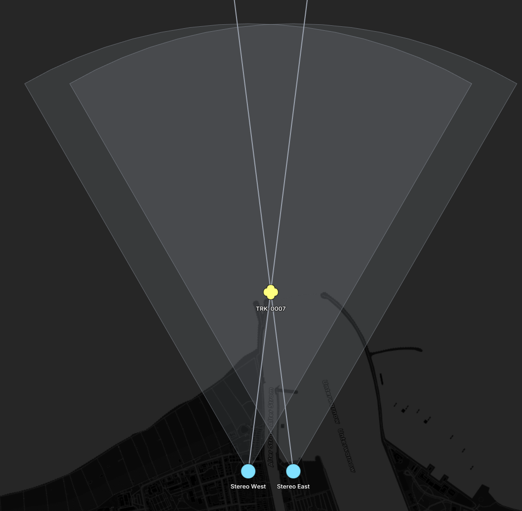
One camera gives a direction. Two cameras that see the same object give two directions that cross, and the crossing point is the position.
The detectors here push no angle at all. Each one reports the pixel box it found, because pixels are what a detector has. The engine takes the field of view and the frame size from the camera, and calculates the bearing with a pinhole model. The fusion engine then crosses the two bearings.
The covariance on the result is the geometry of the measurement. Both cameras stand 808 m from the object and know their angle to 0.5°. That gives 5 m of error across the line of sight and 40 m along it. A short baseline always produces an ellipse that is long in the viewing direction. To reduce the depth error, move the cameras further apart.
hydris ec apply stereo-vision.yaml# Stereo vision: two cameras, and a fusion engine that triangulates them.
#
# Five entities:
# example.stereo.cam.west the left camera
# example.stereo.cam.east the right camera, 202 m east of it
# example.stereo.det.west what the left camera saw
# example.stereo.det.east what the right camera saw
# example.stereo.track.1 the position both bearings agree on
#
# One camera gives a direction and no distance. Two cameras that see the same
# object give two directions that cross. The point where they cross is the
# position. This is the smallest useful fusion in the system, and it needs no
# new component.
#
# Three jobs stay separate, and each part writes only what it knows:
# the detector reports a pixel box
# the engine converts the pixel box into a bearing
# the fusion engine crosses two bearings and pushes the position
#
# Neither camera knows that the other exists. A third camera adds a third
# detection, and only the fusion engine changes.
#
# push it with: hydris ec apply stereo-vision.yaml
---
# The left camera.
id: example.stereo.cam.west
label: Stereo West
geo:
latitude: 54.1800
longitude: 12.0860
altitude: 12
camera:
fov: 60
range_max: 2000
streams:
- label: Main
url: rtsp://stereo-west.example.org/main
protocol: MediaStreamProtocolRtsp
role: MediaStreamRoleMain
codec: H264
device:
class: camera
category: Ground
state: DeviceStateActive
unique_hardware_id: stereo.west.7731
link:
status: LinkStatusConnected
avg_latency_ms: 12
classification:
taxonomy:
- confidence:
confidence: 1.0
equipment:
sensor:
emplaced: {}
electro_optical: {}
symbol:
milStd2525C: SFGPE-----
routing:
channels:
- {}
---
# The right camera. 202 m east of the left one.
# The distance between the two cameras is the baseline. A long baseline gives
# a good position. A short baseline gives a long, thin error ellipse.
id: example.stereo.cam.east
label: Stereo East
geo:
latitude: 54.1800
longitude: 12.0891
altitude: 12
camera:
fov: 60
range_max: 2000
streams:
- label: Main
url: rtsp://stereo-east.example.org/main
protocol: MediaStreamProtocolRtsp
role: MediaStreamRoleMain
codec: H264
device:
class: camera
category: Ground
state: DeviceStateActive
unique_hardware_id: stereo.east.7732
link:
status: LinkStatusConnected
avg_latency_ms: 11
classification:
taxonomy:
- confidence:
confidence: 1.0
equipment:
sensor:
emplaced: {}
electro_optical: {}
symbol:
milStd2525C: SFGPE-----
routing:
channels:
- {}
---
# What the left camera saw.
#
# The detector reports pixels, because pixels are what it has. It pushes no
# pose and no angle at all.
#
# The engine reads `image_bbox`, takes the field of view and the frame size
# from the camera, and calculates the pose with a pinhole model. It adds the
# current pan and tilt of the camera. Here the box centre sits 419 px right
# of the centre of a 3840 px frame at 60 degrees, which is 7.181 degrees.
#
# The engine also converts the width and the height of the box into the
# angular size of the object.
id: example.stereo.det.west
label: Contact (west)
controller:
id: example.detector.yolo
priority: PriorityImmediate
detection:
detectorEntityId: example.stereo.cam.west
confidence: 0.82
image_bbox:
x: 2294
y: 975
width: 90
height: 210
frame_width: 3840
frame_height: 2160
classification:
taxonomy:
- confidence:
confidence: 0.8
vehicle:
land:
multi_wheeled: {}
routing:
channels:
- {}
---
# What the right camera saw: the same object, from 202 m away.
#
# The box sits left of centre here, so the engine calculates 352.819 degrees.
# The two bearings differ by 14.4 degrees, and that angle is the measurement.
id: example.stereo.det.east
label: Contact (east)
controller:
id: example.detector.yolo
priority: PriorityImmediate
detection:
detectorEntityId: example.stereo.cam.east
confidence: 0.79
image_bbox:
x: 1456
y: 975
width: 90
height: 210
frame_width: 3840
frame_height: 2160
classification:
taxonomy:
- confidence:
confidence: 0.75
vehicle:
land:
multi_wheeled: {}
routing:
channels:
- {}
---
# The fused result: the point where the two bearings cross.
#
# The fusion engine reads both detections, intersects the two lines, and
# pushes this entity. `evidence` names the two detections, so an operator can
# ask which cameras produced this position, and a later fuser can re-use them.
#
# The covariance is the interesting part. Both cameras are 808 m from the
# object and know their angle to 0.5 degrees. That gives 5 m of error across
# the line of sight, and 40 m along it. A short baseline always makes the
# ellipse long in the viewing direction. To improve the depth, move the
# cameras apart. To improve both, add a third camera.
id: example.stereo.track.1
label: TRK-0007
controller:
id: example.fusion.stereo
track:
# which fusion engine produced this
tracker: example.fusion.stereo
confidence: 0.88
evidence:
- example.stereo.det.west
- example.stereo.det.east
geo:
latitude: 54.1872
longitude: 12.08755
altitude: 12
# meters squared, local ENU frame. xx=east, yy=north
covariance:
mxx: 25
myy: 1590
classification:
taxonomy:
- confidence:
confidence: 0.85
vehicle:
land:
multi_wheeled: {}
symbol:
milStd2525C: SUGPU-----
routing:
channels:
- {}Time of arrival
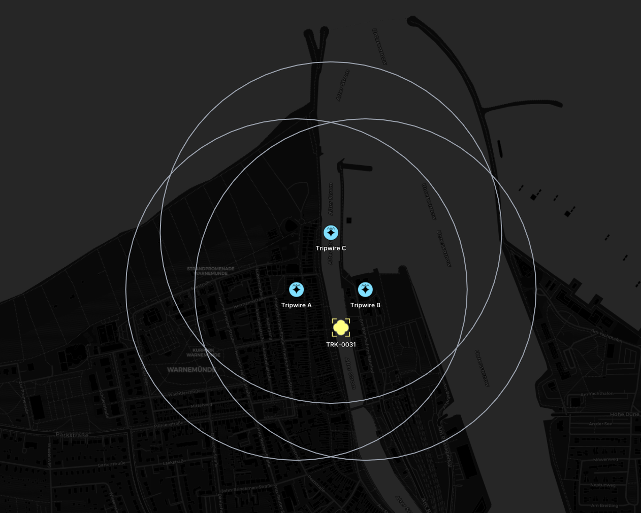
A tripwire cannot give a direction or a distance. It reports that a sound reached it, and when. Sound travels 343 m each second, so a difference between two arrival times is a difference in distance. Three sensors that are not in one line give two independent differences, which is enough to solve for the position and for the moment of the event.
The measurement is the timestamp, so each sensor puts its arrival time in lifetime.fresh. That is the field for when an observation happened.
The event in this file lies south of all three sensors, outside the triangle they form. Nothing in the input says that. It comes only from the order of the three arrival times, and from the gaps between them.
The covariance follows from the clock. These sensors share time to about 10 ms over a radio, and 10 ms of sound is 3.4 m. That gives 4.5 m of error east and 16.9 m north. The ellipse points north because all three sensors measure the distance to the south in nearly the same direction. An event inside the triangle gives a round ellipse. Better clocks give a smaller one.
hydris ec apply time-of-arrival.yaml# Time of arrival: three tripwire sensors, and the event that made them fire.
#
# Seven entities:
# example.toa.wire.a a tripwire sensor
# example.toa.wire.b a tripwire sensor, 202 m east of A
# example.toa.wire.c a tripwire sensor, 195 m north of A
# example.toa.det.b B heard something first, at 09:14:02.386
# example.toa.det.a A heard it 114 ms later, at 09:14:02.500
# example.toa.det.c C heard it last, at 09:14:02.816
# example.toa.track.1 where the sound came from
#
# The event is south of all three sensors, outside the triangle they form.
# Nothing in the input says that. It comes only from the order of the three
# arrival times, and from the gaps between them.
#
# One tripwire cannot say where a sound came from. It says only that a sound
# reached it, and when. Sound travels 343 m each second, so the difference
# between two arrival times is a difference in distance. Three sensors give
# two independent differences, which is enough for a position in two
# dimensions. The fusion engine solves for the position and the moment of the
# event together.
#
# The measurement is the timestamp. Each sensor puts its arrival time in
# `lifetime.fresh`, which is the field for when an observation happened.
#
# push it with: hydris ec apply time-of-arrival.yaml
---
# Sensor A.
id: example.toa.wire.a
label: Tripwire A
geo:
latitude: 54.1800
longitude: 12.0860
altitude: 4
device:
class: tripwire
category: Ground
state: DeviceStateActive
unique_hardware_id: a84041c6545d1401
link:
status: LinkStatusConnected
rssi_dbm: -88
power:
battery_charge_remaining: 0.76
voltage: 3.9
classification:
taxonomy:
- confidence:
confidence: 1.0
equipment:
sensor:
emplaced: {}
acoustic: {}
symbol:
milStd2525C: SFGPESE---
routing:
channels:
- {}
---
# Sensor B, 202 m east of A.
id: example.toa.wire.b
label: Tripwire B
geo:
latitude: 54.1800
longitude: 12.0891
altitude: 4
device:
class: tripwire
category: Ground
state: DeviceStateActive
unique_hardware_id: a84041c6545d1402
link:
status: LinkStatusConnected
rssi_dbm: -91
power:
battery_charge_remaining: 0.71
voltage: 3.8
classification:
taxonomy:
- confidence:
confidence: 1.0
equipment:
sensor:
emplaced: {}
acoustic: {}
symbol:
milStd2525C: SFGPESE---
routing:
channels:
- {}
---
# Sensor C, 195 m north of A. Three sensors that are not in one line give a
# position. Three sensors in one line do not.
id: example.toa.wire.c
label: Tripwire C
geo:
latitude: 54.1815
longitude: 12.08755
altitude: 4
device:
class: tripwire
category: Ground
state: DeviceStateActive
unique_hardware_id: a84041c6545d1403
link:
status: LinkStatusConnected
rssi_dbm: -84
power:
battery_charge_remaining: 0.80
voltage: 3.9
classification:
taxonomy:
- confidence:
confidence: 1.0
equipment:
sensor:
emplaced: {}
acoustic: {}
symbol:
milStd2525C: SFGPESE---
routing:
channels:
- {}
---
# What sensor A reported. The sound reached it 114 ms after B.
#
# The sensor knows the time, and nothing else. It cannot give a direction or a
# distance, so the detection sits on the sensor inside a large circle. Do not
# guess a position here. The circle is honest, and the fusion engine replaces
# it with a real one.
id: example.toa.det.a
label: Acoustic Trip A
controller:
id: example.toa.wire.a
priority: PriorityImmediate
# the arrival time. this is the whole measurement
lifetime:
fresh: "2026-03-01T09:14:02.500Z"
detection:
detectorEntityId: example.toa.wire.a
confidence: 0.6
pose:
parent: example.toa.wire.a
cartesian:
covariance:
mxx: 250000
myy: 250000
routing:
channels:
- {}
---
# What sensor B reported. It is nearest to the event, so it heard the sound
# first.
id: example.toa.det.b
label: Acoustic Trip B
controller:
id: example.toa.wire.b
priority: PriorityImmediate
lifetime:
fresh: "2026-03-01T09:14:02.386Z"
detection:
detectorEntityId: example.toa.wire.b
confidence: 0.5
pose:
parent: example.toa.wire.b
cartesian:
covariance:
mxx: 250000
myy: 250000
routing:
channels:
- {}
---
# What sensor C reported. It is the furthest away, so it heard the sound last,
# 430 ms after B. That large gap is what puts the event south of the others.
id: example.toa.det.c
label: Acoustic Trip C
controller:
id: example.toa.wire.c
priority: PriorityImmediate
lifetime:
fresh: "2026-03-01T09:14:02.816Z"
detection:
detectorEntityId: example.toa.wire.c
confidence: 0.7
pose:
parent: example.toa.wire.c
cartesian:
covariance:
mxx: 250000
myy: 250000
routing:
channels:
- {}
---
# The fused result.
#
# The fusion engine reads the three arrival times, solves for the position and
# the moment of the event, and pushes this entity.
#
# The output is a track. A detection is what one sensor measured. A track is a
# located thing, and the rule is that simple: if you can say where it is, it
# is a track. Three tripwires that could each say only "something is near me"
# become one point that a person can act on.
#
# `track.evidence` names the three detections, so an operator can ask which
# sensors produced this point, and a later stage can use them again.
#
# `lifetime.fresh` holds the moment the fusion engine solved for. It is 386 ms
# before the first sensor heard anything, because the sound needed that long
# to travel 132 m.
#
# The covariance follows from the clock. These sensors share time over a radio
# to about 10 ms, and 10 ms of sound is 3.4 m. The result is 4.5 m of error
# east and 16.9 m north. The ellipse points north because the event lies south
# of all three sensors. All three measure the distance to the south in nearly
# the same direction, so nothing constrains it well. An event inside the
# triangle gives a round ellipse. Better clocks give a smaller one.
#
# There is no symbol here. The classification is still pending, so the engine
# derives a pending symbol from the taxonomy.
id: example.toa.track.1
label: TRK-0031
controller:
id: example.fusion.toa
lifetime:
fresh: "2026-03-01T09:14:02.000Z"
track:
# which fusion engine produced this
tracker: example.fusion.toa
confidence: 0.83
evidence:
- example.toa.det.a
- example.toa.det.b
- example.toa.det.c
geo:
latitude: 54.1790
longitude: 12.0880
altitude: 4
# meters squared, local ENU frame. xx=east, yy=north, xy=correlation
covariance:
mxx: 20.1
myy: 285.5
mxy: -42.2
classification:
taxonomy:
- confidence:
confidence: 0.5
pending: true
person: {}
routing:
channels:
- {}Vehicles
Ship
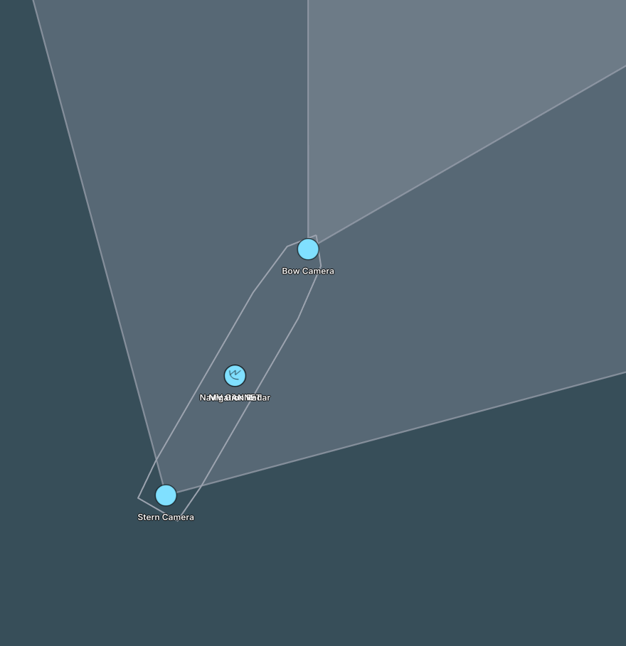
A hull, its outline, two fixed cameras and a navigation radar. Each part gives an offset in meters from the ship.
The hull has an orientation. The engine rotates the offset of each child by it. The bow camera stays at the bow through a turn, and its coverage cone turns with the ship. A driver that receives a new position and heading pushes two components on one entity, and the other five entities follow.
Watch the sign of the quaternion. A bearing runs clockwise from north, and quaternion yaw runs counter-clockwise. A heading of 030 is z = sin(-15°), not sin(15°).
The two sensors declare their coverage in different ways. The cameras give a fov and a range_max, and the engine builds the cone. The engine cannot guess the shape of the radar coverage, so sensor.coverage names a shape entity that gives it.
hydris ec apply ship.yaml# A vessel and everything bolted to it.
#
# The mast in camera-tower.yaml is a pose tree that never moves. This is the
# same idea on something that does: one hull, its outline, two fixed cameras
# and a navigation radar, all declared as offsets in meters from the ship.
#
# The hull carries the only latitude and longitude in the file, and an
# orientation. Because the children hang off it by pose, the engine rotates
# their offsets by the ship's heading before resolving them - so the bow camera
# stays at the bow when the ship turns, and its coverage cone swings with it.
# A driver that receives a new position and heading pushes two components on
# one entity, and the whole assembly follows.
#
# `assembly` is what ties the parts together for a UI: the hull points at its
# outline, each part points back at the hull as its parent, so an operator can
# select the ship and see its sensors, or select a sensor and know whose it is.
#
# push it with: hydris ec apply ship.yaml
---
# The platform itself.
id: example.ship.gannet
label: MV GANNET
geo:
latitude: 54.2050
longitude: 12.0980
altitude: 0
# heading 030, as a quaternion about the up axis. bearings are clockwise from
# north while quaternion yaw is counter-clockwise, so the z term is negative:
# z = sin(-heading/2), w = cos(-heading/2).
# everything below is positioned relative to this
orientation:
orientation: { x: 0, y: 0, z: -0.2588, w: 0.9659 }
kinematics:
velocityEnu:
east: 1.5
north: 2.6
# overall extent, used for scale and collision-ish reasoning
bounds:
width_m: 32
height_m: 200
depth_m: 12
# our platform, so it is an asset with a state. the sensors below name it as
# their device parent, which puts the whole vessel in the device tree
device:
class: vessel
category: Sea
state: DeviceStateActive
# the parts of this assembly that draw its outline
assembly:
outline:
- example.ship.gannet.hull
classification:
taxonomy:
- confidence:
confidence: 1.0
vehicle:
sea: {}
symbol:
milStd2525C: SFSPXM----
routing:
channels:
- {}
---
# The hull outline, drawn in the ship's own frame: north is forward, east is
# starboard, in meters. A 200 m vessel with a pointed bow at +100.
# The engine converts this to WGS84 and re-converts it whenever the ship moves.
id: example.ship.gannet.hull
local_shape:
relative_to: example.ship.gannet
geometry:
polygon:
outer:
points:
- { east_m: 0, north_m: 100 }
- { east_m: 12, north_m: 85 }
- { east_m: 16, north_m: 50 }
- { east_m: 16, north_m: -70 }
- { east_m: 14, north_m: -95 }
- { east_m: -14, north_m: -95 }
- { east_m: -16, north_m: -70 }
- { east_m: -16, north_m: 50 }
- { east_m: -12, north_m: 85 }
- { east_m: 0, north_m: 100 }
routing:
channels:
- {}
---
# Forward-looking camera, 90 m ahead of the ship's origin and 15 m up.
# Fixed, not PTZ: no focal point, so its coverage cone points wherever the
# hull is pointing.
id: example.ship.gannet.cam.bow
label: Bow Camera
assembly:
parent: example.ship.gannet
# `assembly.parent` is the physical grouping for an operator, `device.parent`
# is the tree the engine and the configuration UI walk. Here they agree,
# but they answer different questions and often do not.
device:
parent: example.ship.gannet
class: camera
state: DeviceStateActive
pose:
parent: example.ship.gannet
cartesian:
east_m: 0
north_m: 90
up_m: 15
camera:
fov: 60
range_max: 5000
streams:
- label: Bow
url: rtsp://gannet.example.org/bow
protocol: MediaStreamProtocolRtsp
role: MediaStreamRoleMain
codec: H264
classification:
taxonomy:
- confidence:
confidence: 1.0
equipment:
sensor:
electro_optical: {}
symbol:
milStd2525C: SFGPE-----
routing:
channels:
- {}
---
# Aft-facing camera, wider and shorter ranged.
id: example.ship.gannet.cam.stern
label: Stern Camera
assembly:
parent: example.ship.gannet
device:
parent: example.ship.gannet
class: camera
state: DeviceStateActive
pose:
parent: example.ship.gannet
cartesian:
east_m: 0
north_m: -85
up_m: 10
camera:
fov: 90
range_max: 3000
streams:
- label: Stern
url: rtsp://gannet.example.org/stern
protocol: MediaStreamProtocolRtsp
role: MediaStreamRoleMain
codec: H264
classification:
taxonomy:
- confidence:
confidence: 1.0
equipment:
sensor:
electro_optical: {}
symbol:
milStd2525C: SFGPE-----
routing:
channels:
- {}
---
# Navigation radar on the mast, 25 m above the waterline.
# Unlike a camera, its coverage is not derived from a field of view - it points
# at shape entities that describe it, which is how any sensor with a coverage
# footprint the engine cannot guess declares one.
id: example.ship.gannet.radar
label: Navigation Radar
assembly:
parent: example.ship.gannet
device:
parent: example.ship.gannet
class: radar
state: DeviceStateActive
pose:
parent: example.ship.gannet
cartesian:
east_m: 0
north_m: 0
up_m: 25
sensor:
coverage:
- example.ship.gannet.radar.coverage
classification:
taxonomy:
- confidence:
confidence: 1.0
equipment:
sensor:
radar: {}
symbol:
milStd2525C: SFGPESR---
routing:
channels:
- {}
---
# 20 km all-round radar coverage, again in the ship's frame so it travels
# with the hull.
id: example.ship.gannet.radar.coverage
local_shape:
relative_to: example.ship.gannet
geometry:
circle:
center: { east_m: 0, north_m: 0 }
radius_m: 20000
extrusion:
fill:
color: "#38bdf8"
opacity: 0.06
routing:
channels:
- {}UAV
Telemetry from an unmanned aircraft, at the rate a MAVLink driver pushes it. Each subsystem has its own component: battery, link quality, GNSS fix and mission progress. A UI shows all of it and knows nothing about aircraft. The same power and link components mean the same thing on a boat, a radio or a ground robot.
hydris ec apply uav.yaml# Live telemetry from an unmanned aircraft.
#
# This is the shape of entity a MAVLink or vendor driver pushes a few times per
# second. Every subsystem gets its own component, so a UI can show battery,
# link quality and mission progress without a bespoke drone schema - and the
# same components mean the same thing on a boat, a radio or a ground robot.
#
# push it with: hydris ec apply uav.yaml
id: example.uav.spectre
label: SPECTRE-1
geo:
latitude: 54.1866
longitude: 12.0952
altitude: 118
# full 3D attitude as a unit quaternion. the outer key is the component,
# the inner one is the field inside it.
# this is a heading of 030: quaternion yaw runs counter-clockwise while
# bearings run clockwise from north, so z = sin(-heading/2)
orientation:
orientation: { x: 0, y: 0, z: -0.2588, w: 0.9659 }
# heading only, for consumers that do not care about roll and pitch
bearing:
azimuth: 30
kinematics:
# ground-referenced velocity in m/s, NOT body frame
velocityEnu:
east: 8.1
north: 14.0
up: 0.4
angularVelocityBody:
roll_rate: 0
pitch_rate: 0
yaw_rate: 0.12
navigation:
mode: NavigationModeAutonomous
armed: true
waypoint_current: 3
waypoint_total: 7
power:
battery_charge_remaining: 0.62
voltage: 22.4
current_a: 18.7
remaining_seconds: 900
gnss:
fix_type: GnssFixTypeRtkFixed
satellites_visible: 24
satellites_used: 19
hdop: 0.7
# our aircraft, so it gets a device component and shows up as an asset with a
# readiness state: positioned, device active, link connected
device:
class: uav
category: Air
state: DeviceStateActive
unique_hardware_id: spectre.0f31a7
link:
status: LinkStatusConnected
rssi_dbm: -67
snr_db: 14
link_quality_percent: 92
rf_mode: 50Hz
packet_rate_hz: 50
classification:
taxonomy:
- confidence:
confidence: 1.0
vehicle:
unmanned: {}
air:
rotary: {}
administrative:
manufacturer: Example Robotics
model: Spectre 4
owner: Team North
symbol:
milStd2525C: SFAPMFQ---
routing:
channels:
- {}A contact from AIS
The two files above are vehicles you control. This one is a vehicle you only watch. Almost nothing in it is maritime. geo, bearing and kinematics are the components the UAV uses. Only transponder holds the AIS data. An aircraft from ADS-B is the same entity with transponder.adsb.
It has no device component, because you do not own it.
hydris ec apply vessel.yaml# A ship built from an AIS message.
#
# Note how little of this is maritime-specific: geo, bearing and kinematics are
# the same components a drone uses. Only `transponder` carries the AIS payload.
# An ADS-B aircraft is the same entity with transponder.adsb instead.
#
# push it with: hydris ec apply vessel.yaml
id: example.vessel.aurora
label: AURORA
geo:
latitude: 54.2210
longitude: 12.1440
bearing:
azimuth: 212
kinematics:
velocityEnu:
east: -3.1
north: -4.9
transponder:
ais:
mmsi: 211234560
imo: 9312345
callsign: DHAU
vessel_name: AURORA
# static hull data from the AIS class A report
administrative:
flag: DE
owner: Example Shipping GmbH
length_m: 154.0
width_m: 23.5
tonnage_gt: 18700
year_built: 2011
navigation:
mode: NavigationModeUnderway
# voyage data. timestamps are RFC 3339 strings, always UTC
mission:
destination: ROSTOCK
eta: "2035-06-01T08:30:00Z"
classification:
taxonomy:
- confidence:
confidence: 1.0
vehicle:
sea: {}
symbol:
milStd2525C: SNSP------
routing:
channels:
- {}Team
A person is an entity, and a person carries equipment. The equipment attaches to the person exactly as the ship sensors attach to the hull.
Three components do three different jobs, and a UI uses all three:
posegives where the device sits on the person, so it moves with them.assemblysays which person the device is part of.device.parentputs the device under the person in the device tree.
The mission component on the team leader names the members, the task and the destination. That is what makes two people a team.
Chat is also an entity, so a message uses the same routing, priority and lifetime as everything else. A bridge can carry it to TAK, to Meshtastic or to a radio. sender and to hold entity ids, not names.
hydris ec apply team.yaml# A team on foot, with the kit each person carries.
#
# Eight entities:
# example.team.alpha.camp the base the team works from
# example.team.alpha.alice the team leader
# example.team.alpha.bob a team member
# example.team.alpha.alice.vitals her vital signs monitor
# example.team.alpha.alice.wind her wind sensor
# example.team.alpha.alice.radio her radio
# example.team.alpha.chat.1 a message she sent
# example.team.alpha.chat.2 the answer
#
# A person is an entity like any other. A person carries devices, so the
# devices attach to the person in the same way that the ship sensors attach to
# the hull: `pose` for where the device sits, `assembly` for what it is part
# of, and `device.parent` for the device tree.
#
# Bob carries the same kit. This file gives it to Alice only, to stay short.
#
# push it with: hydris ec apply team.yaml
---
# The base. The team leader and the radios refer to it.
id: example.team.alpha.camp
label: Base Camp
geo:
latitude: 54.1770
longitude: 12.0840
altitude: 5
device:
class: camp
category: Ground
state: DeviceStateActive
classification:
taxonomy:
- confidence:
confidence: 1.0
infrastructure: {}
symbol:
milStd2525C: SFGPU-----
routing:
channels:
- {}
---
# The team leader.
#
# The mission component makes this a team rather than two separate people.
# It names the members, the task and the destination. Put it on the leader.
id: example.team.alpha.alice
label: Alpha - Alice
geo:
latitude: 54.1795
longitude: 12.0902
altitude: 12
kinematics:
velocityEnu:
east: 0.9
north: 1.1
up: 0.1
mission:
members:
- example.team.alpha.alice
- example.team.alpha.bob
description: Shore patrol, north perimeter
destination: North Mast
device:
parent: example.team.alpha.camp
class: person
category: Ground
state: DeviceStateActive
classification:
taxonomy:
- confidence:
confidence: 1.0
person: {}
symbol:
milStd2525C: SFGPUC----
routing:
channels:
- {}
---
# A team member. Same shape, no mission component.
id: example.team.alpha.bob
label: Alpha - Bob
geo:
latitude: 54.1791
longitude: 12.0897
altitude: 11
kinematics:
velocityEnu:
east: 1.0
north: 0.8
device:
parent: example.team.alpha.camp
class: person
category: Ground
state: DeviceStateActive
classification:
taxonomy:
- confidence:
confidence: 1.0
person: {}
symbol:
milStd2525C: SFGPUC----
routing:
channels:
- {}
---
# Vital signs from a chest strap.
#
# `pose` puts the device on the person, so it moves with her. `assembly` says
# it is part of her kit. `device.parent` puts it under her in the device tree.
# The three answer different questions, and a UI uses all three.
id: example.team.alpha.alice.vitals
label: Alice Vital Monitor
assembly:
parent: example.team.alpha.alice
device:
parent: example.team.alpha.alice
class: vitals
state: DeviceStateActive
pose:
parent: example.team.alpha.alice
cartesian:
east_m: 0.1
north_m: 0
up_m: 0.4
# an empty sensor component marks the entity as a sensor
sensor: {}
metric:
metrics:
- id: 1
kind: MetricKindHeartRate
unit: MetricUnitBeatsPerMinute
label: Heart Rate
double: 118
alerting: AlertLevelWarning
range:
min_double: 40
max_double: 200
- id: 2
kind: MetricKindOxygenSaturation
unit: MetricUnitPercent
label: SpO2
double: 94
- id: 3
kind: MetricKindBodyTemperature
unit: MetricUnitCelsius
label: Body Temperature
double: 37.1
classification:
taxonomy:
- confidence:
confidence: 1.0
equipment:
sensor: {}
routing:
channels:
- {}
---
# A wind sensor on top of the backpack.
id: example.team.alpha.alice.wind
label: Alice Wind Sensor
assembly:
parent: example.team.alpha.alice
device:
parent: example.team.alpha.alice
class: weather
state: DeviceStateActive
pose:
parent: example.team.alpha.alice
cartesian:
east_m: 0
north_m: 0
up_m: 0.3
sensor: {}
metric:
metrics:
- id: 1
kind: MetricKindWindSpeed
unit: MetricUnitMeterPerSecond
label: Wind Speed
double: 12.4
- id: 2
kind: MetricKindWindDirection
unit: MetricUnitDegree
label: Wind Direction
double: 285
classification:
taxonomy:
- confidence:
confidence: 1.0
equipment:
sensor: {}
routing:
channels:
- {}
---
# The radio on her hip.
#
# `link.via` names the entity on the other end. That is how a client draws the
# radio network, and how it explains a lost link.
id: example.team.alpha.alice.radio
label: Alice Radio
assembly:
parent: example.team.alpha.alice
device:
parent: example.team.alpha.alice
class: radio
state: DeviceStateActive
pose:
parent: example.team.alpha.alice
cartesian:
east_m: 0.15
north_m: 0
up_m: -0.2
link:
status: LinkStatusDegraded
via: example.team.alpha.camp
rssi_dbm: -97
snr_db: -3
link_quality_percent: 34
power:
battery_charge_remaining: 0.41
voltage: 3.7
symbol:
milStd2525C: SFGPE-----
routing:
channels:
- {}
---
# A message.
#
# Chat is an entity, so it uses the same routing, priority and lifetime as
# everything else. A bridge can carry it to TAK, to Meshtastic or to a radio.
# `sender` and `to` are entity ids, not names.
id: example.team.alpha.chat.1
label: Alice
chat:
sender: example.team.alpha.alice
message: Alpha at the north mast, wind is up
priority: PriorityImmediate
routing:
channels:
- {}
---
# The answer. `reply_to` links the two.
# A client that has no threads shows this as a normal message.
id: example.team.alpha.chat.2
label: Bob
chat:
sender: example.team.alpha.bob
to: example.team.alpha.alice
reply_to: example.team.alpha.chat.1
message: Copy, hold there. I am 60 m behind you
priority: PriorityImmediate
routing:
channels:
- {}Push entities for real
The examples are complete entities. A live feed does not push that way. Two rules apply.
Push only what changed. Push takes changes and replacements:
changesreplaces each component in your message, and leaves out every component you did not send. A driver that sends{id, geo}at 10 Hz keepslabel,powerandlinkas they were.replacementsreplaces the whole entity. The engine removes every component you did not send.
The engine replaces a whole component. It never merges the fields inside one. If you push a geo with only a latitude, the longitude and the altitude are lost. Read Entity Merge before two controllers write to one entity.
Give short-lived things a lifetime. No example sets lifetime.until, because a fixed time in a file is either in the past or far in the future. A real feed sets one:
lifetime:
  fresh: "2026-03-01T09:14:02Z"   # when the sensor made this observation
  until: "2026-03-01T09:14:32Z"   # gone 30 seconds later, unless something refreshes it
fresh also rejects updates that arrive out of order. The engine drops a push when its fresh is older than the value the component already has. Detections and tracks need both fields. Markers, zones and vehicles usually need neither.